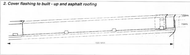
These are used where an EPDM or Fibreglass roof covering turn up against a wall. Code 4 lead sheet is normally used for this work and it is important that the
Length
of each piece of flashing does not exceed 1.5m. Laps between pieces should not
be less than 100mm.
Lead
wedges are simply 25mm wide pieces of lead folded over sufficient times to suit
the
Width
of the mortar joint. The wedges are
driven into the joint with a plugging chisel.
Copper
or stainless steel clips are positioned along the lower edge of the flashing to
suit the exposure of the building
– see Diagram 2.
At internal and external corners the 25mm turn-in is cut and the flashing folded as shown in Diagram 3. Note that the lap joint is adjacent to the corner and NOT in the corner. The turn-in on the external corner is simply folded as shown whereas it is necessary to insert a small piece of lead in the internal corner to ensure a weathertight joint. This can be achieved by either lead wielding or soldering.

The
extension under the tiles is 100mm. A soaker is held in place by turning the top
edge over the tile. The upstands are not fixed but are made
weathertight with a Code
4 flashing. Diagram 6.
Setting
out the flashing is achieved by first marking the water line on a length of lead
65mm from the lower edge. No cuts are made below this line. The lead is held
against the wall and the mortar joint lines are marked as also shown in diagram
6. An allowance of 25mm is made for turning each step into the wall and the
surplus area then cut out. After bending, each step is wedged into the wall.
Points
to note are that no piece of
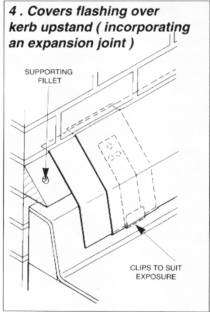
Where
the roof incorporates an expansion joint the flashings are detailed as shown in
Diagram 4. Without the fillet the lead would sag onto the top of the kerb. This
will create a section of horizontal lap through which water will seep into the
area below. The fillet also provides a positive fixing for the clips.